Mechanical Design Portfolio
Precision mechanisms for robust, contact-rich robotic manipulation.
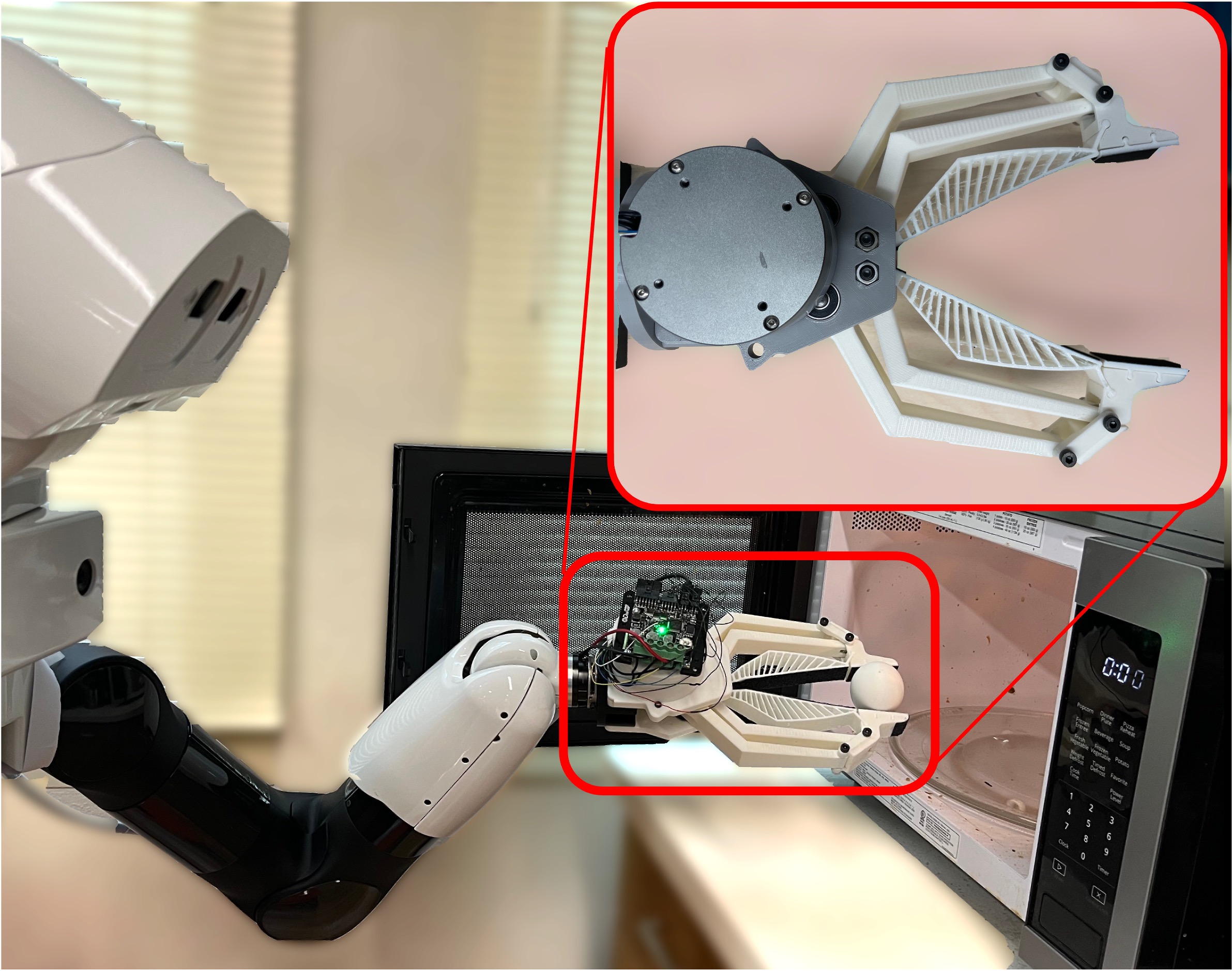
BaRiFlex — High-Transparency Rigid-Flexible Gripper for Crash-Safe Reinforcement Learning
Challenge: Real-world Reinforcement Learning (RL) requires unconstrained exploration, which frequently leads to catastrophic hardware failure in traditional rigid grippers.
Insight: A direct-drive, rigid-flexible hybrid four-bar linkage. It provides the mechanical precision required for fine tasks while acting as a physical safety layer that passively absorbs impact energy.
Led the hardware development from concept to electromechanical bring-up. Executed MATLAB kinematic optimization, 3D CAD modeling (SolidWorks), mechanical fabrication, and low-level motor control integration. Facilitated the Sim-to-Real RL hardware validation conducted by a collaborating researcher. Additionally, authored a comprehensive open-source hardware tutorial and Bill of Materials (BOM) to ensure full reproducibility and ease of integration.
Kinematic & Structural Rationale
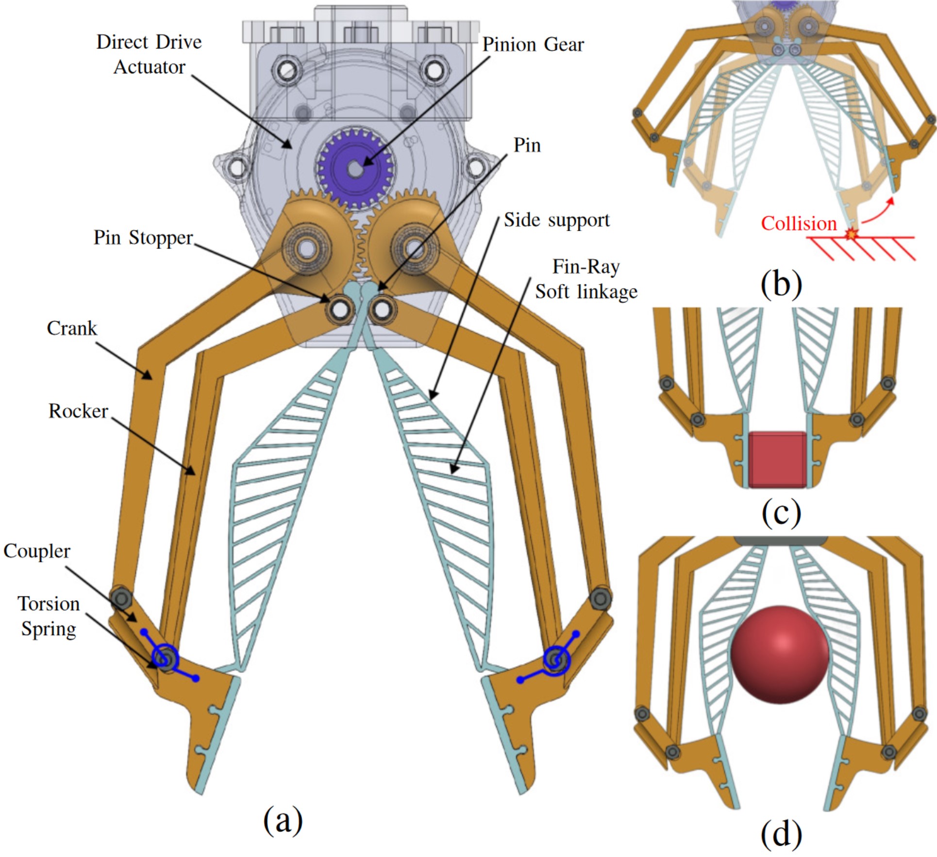
- Four-Bar Linkage Synthesis (Fig. 1a, b): Optimized to maintain consistent force transmission and avoid singularities within a compact operational workspace.
- Compliant Elastomeric Contacts (Fig. 1c, d): Rigid proximal links ensure parallel pinch precision, while Fin-Ray distal fingers provide compliant, conformal grasping and critical impact absorption under dynamic loads.
- Direct-Drive Proprioception: Eliminating the gearbox minimizes inertia and backlash, enabling high-bandwidth force control and high-fidelity proprioceptive force sensing without relying on fragile external F/T sensors.
• Max Stroke: 200 mm
• Closing Time: 0.18 s
• Weight: 750 g
• Gear-Pinion Ratio: 1.54
Performance Matrix
| Metric | Rigid Grippers | Soft Grippers | BaRiFlex |
|---|---|---|---|
| Impact Compliance | Low | High | High (Passively Absorbs) |
| Pinch Precision | High | Low | High (Rigid Base Link) |
| Backdrivability & Sensing | Low (Geared) | N/A | High (Direct-Drive Proprioception) |
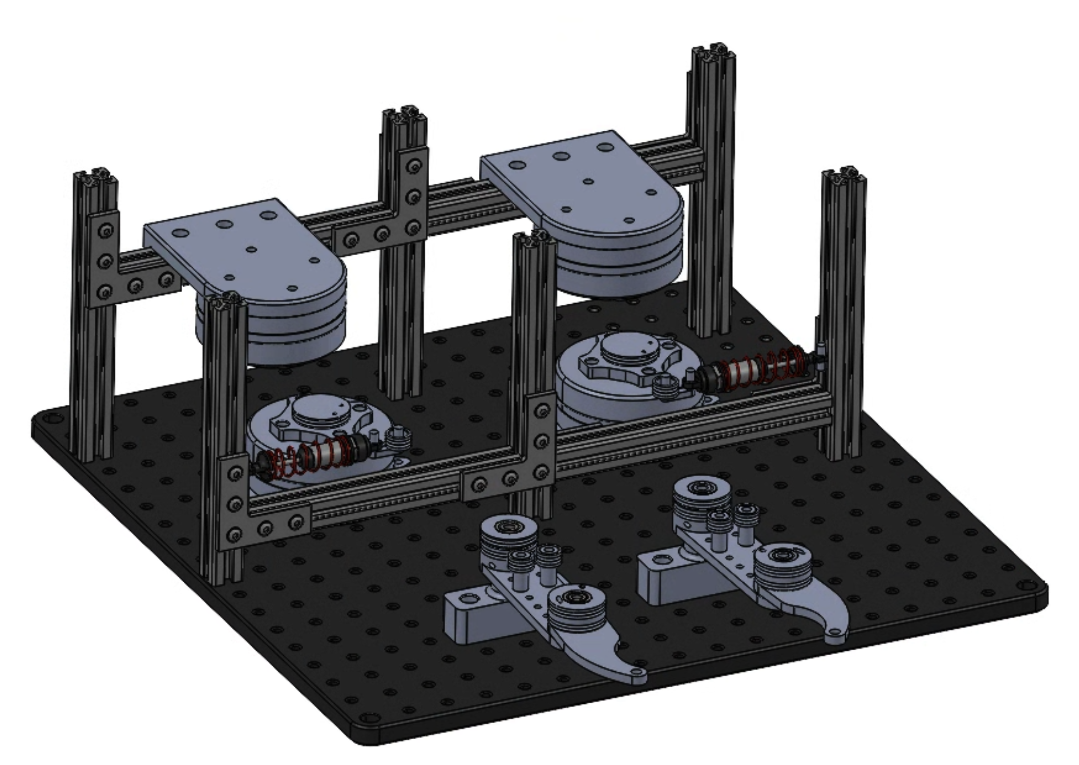
Impact Robustness Validation
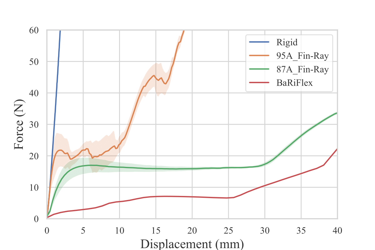
Linear actuator collision tests (Fig. 2) validate a significant reduction in peak impact forces compared to rigid alternatives. The hybrid elastomeric structure passively deforms to protect the motor shaft from shock loads, ensuring durability in demanding use cases.
System Integration: Bridging the Sim-to-Real Gap
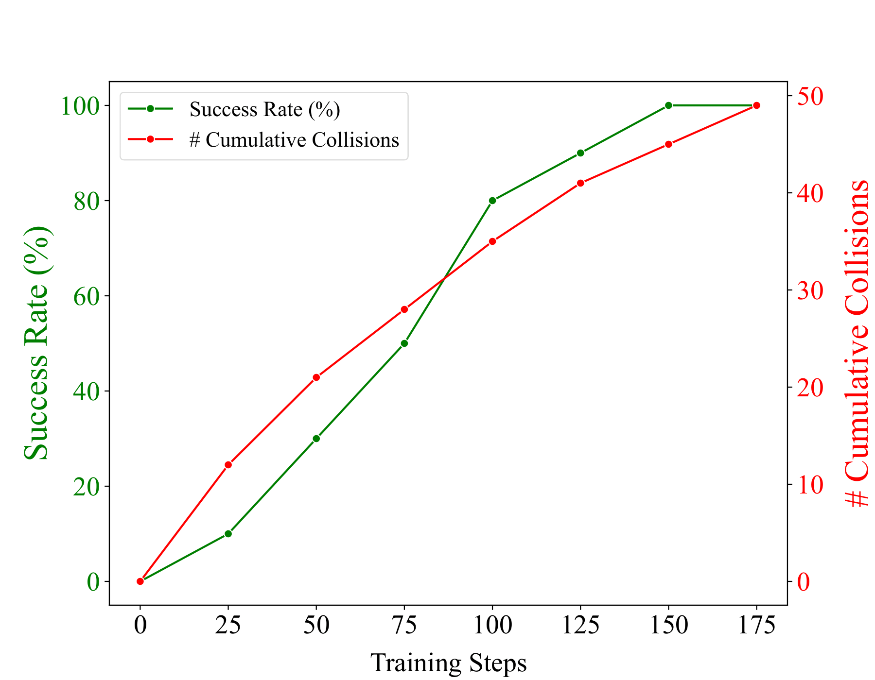
Collaborated with the controls team to validate the hardware in a dynamic environment. During real-world reinforcement learning, BaRiFlex withstood 49 unconstrained, high-speed collisions without structural damage. This robust design provided a physical safety layer, eliminating hardware downtime and enabling aggressive exploration policies to achieve 100% task success.
Repeatability & Precision Measurement
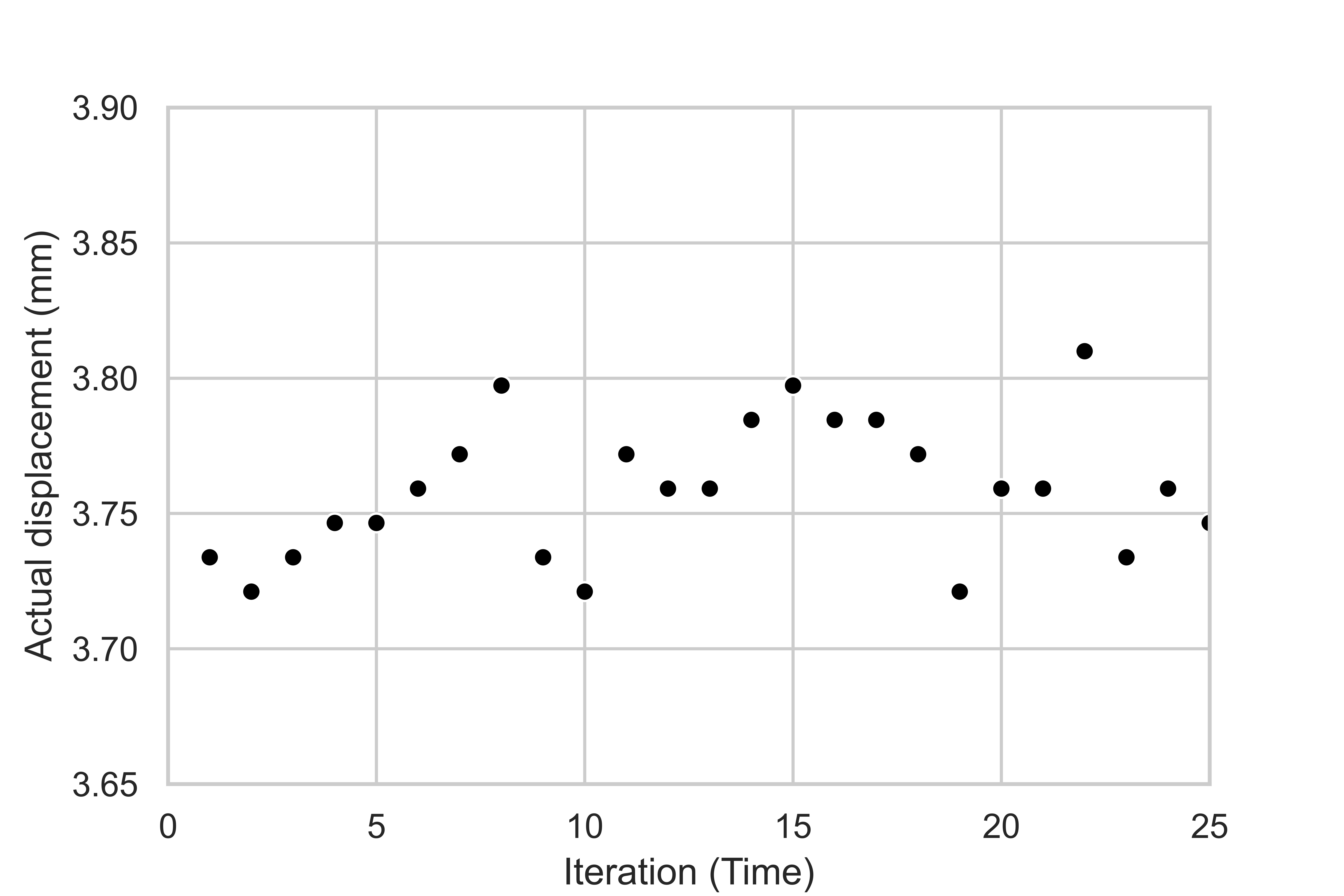
Despite the flexible components, the rigid 4-bar base maintains strict kinematic constraints. As shown in Fig. 3, dial indicator tests across 25 consecutive trials show a maximum deviation of only 0.0889 mm, validating precision manufacturing and assembly.
🏆 Winner: Best Paper on Robot Mechanisms and Design
Underactuated Prosthetic Finger – Precision Linkage Mechanism
Challenge: Restore stable, adaptive, and natural grasping for partial-hand amputees in a compact, wearable form factor without draining battery life during static holds.
Insight: A 3-DOF underactuated mechanism driven by a non-backdrivable lead-screw transmission. It passively conforms to object shapes while holding payloads securely with zero static power consumption.
Engineered the 3-DOF kinematic synthesis and complex assembly modeling with tight packaging constraints. Integrated the SEMG-based standalone hardware/firmware architecture, and led direct patient clinical trials to validate ADL performance.
Kinematic & Structural Rationale
- Design for Manufacturing (DFM): Machined 8 AL6061 components with black anodizing for durability. Applied strict ISO fits (H7/h6), utilized press-fit pins, and secured high-vibration joints with thread-lockers for robust field reliability.
- Energy Efficiency: The non-backdrivable lead-screw ensures the finger holds objects securely without continuous power draw, minimizing thermal load and extending battery life.
• MCP Velocity / Time: 99.4 °/s / 0.83 s
• Battery Life: >3000 cycles
Mathematical Trade-off Optimization
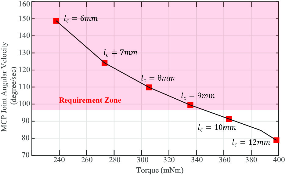
To maximize the pinch force within the constrained space without compromising operational speed, a mathematical relationship between the crank length, MCP torque, and angular velocity was formulated.
Based on this kinematic model, the slider-crank parameter (lc) was optimized to 8 mm. This specific configuration maximizes the torque transmission while successfully satisfying the target >100°/s velocity requirement, demonstrating a rigorous, data-driven approach to mechanism synthesis.
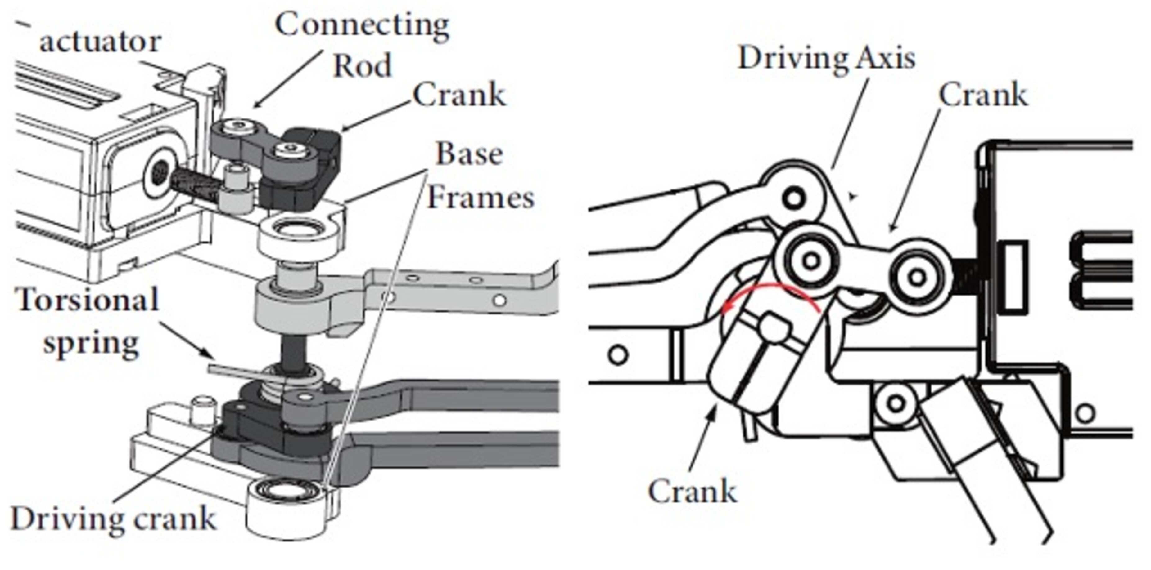
Self-Adaptive Grasping Mechanism
Torsional springs couple the MCP, PIP, and DIP joints, enabling the single-actuator finger to passively conform to various object shapes. This kinetoelastic underactuation distributes motion naturally along the kinematic chain.
A fixed passive thumb was strategically implemented to provide a reliable opposition force for essential pinch and power grasps while minimizing overall prosthesis weight and control complexity.
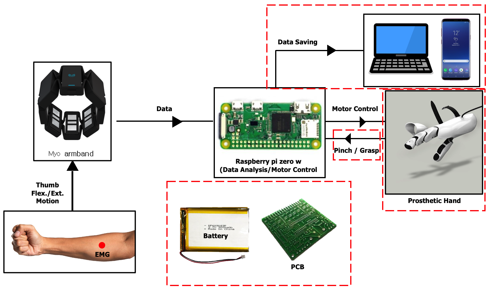
Stand-Alone System Integration
Demonstrated multidisciplinary integration by developing a fully untethered wearable system. It combines an SEMG (Myo) armband, Raspberry Pi Zero, and a custom PCB for real-time intent classification and motor control.
To ensure wearability, the socket was fabricated from lightweight polycarbonate based on a 3D scan of the patient's residual hand. A NATO strap and silicone friction pads were added to prioritize patient comfort and rapid donning/doffing.
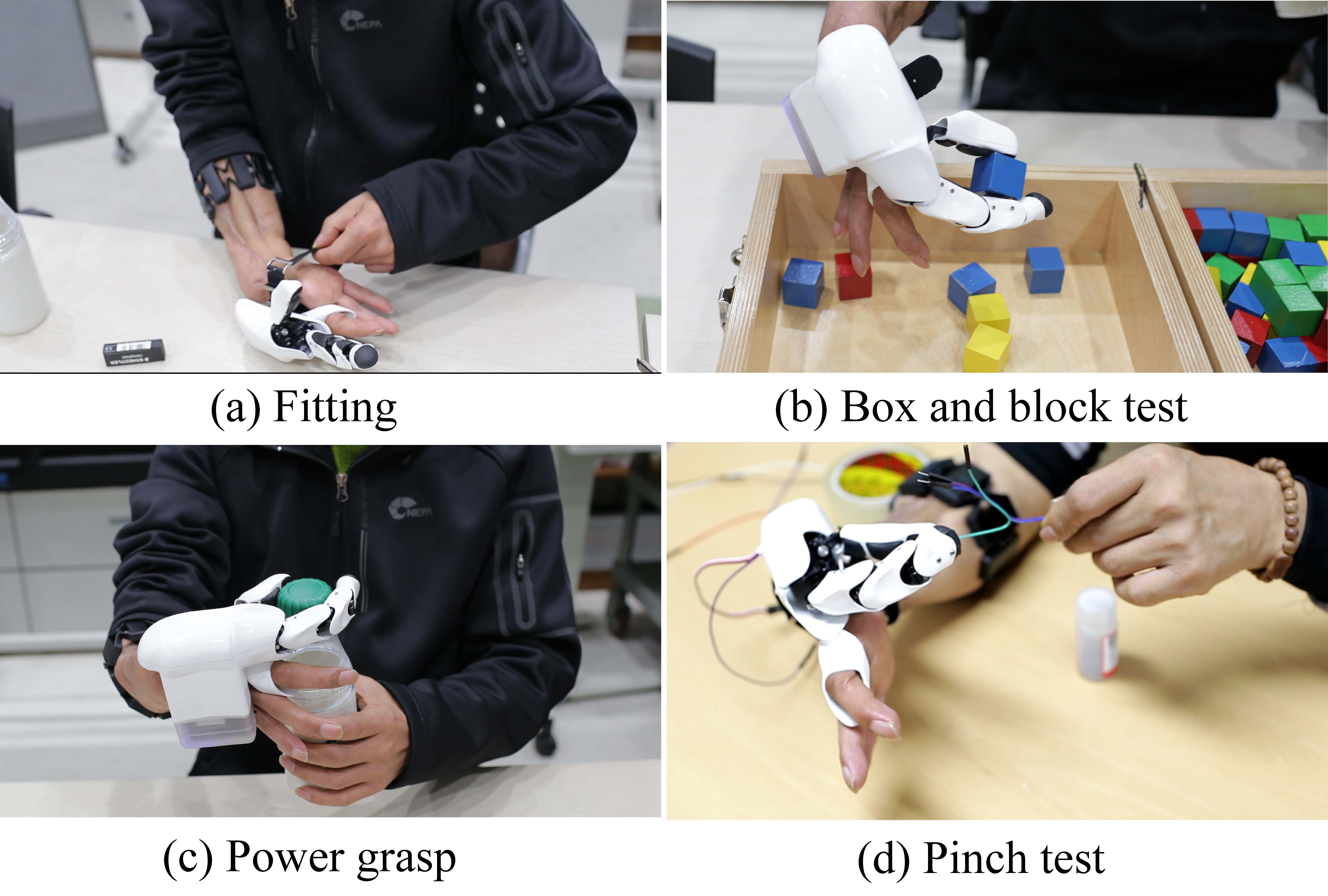
Patient Clinical Validation
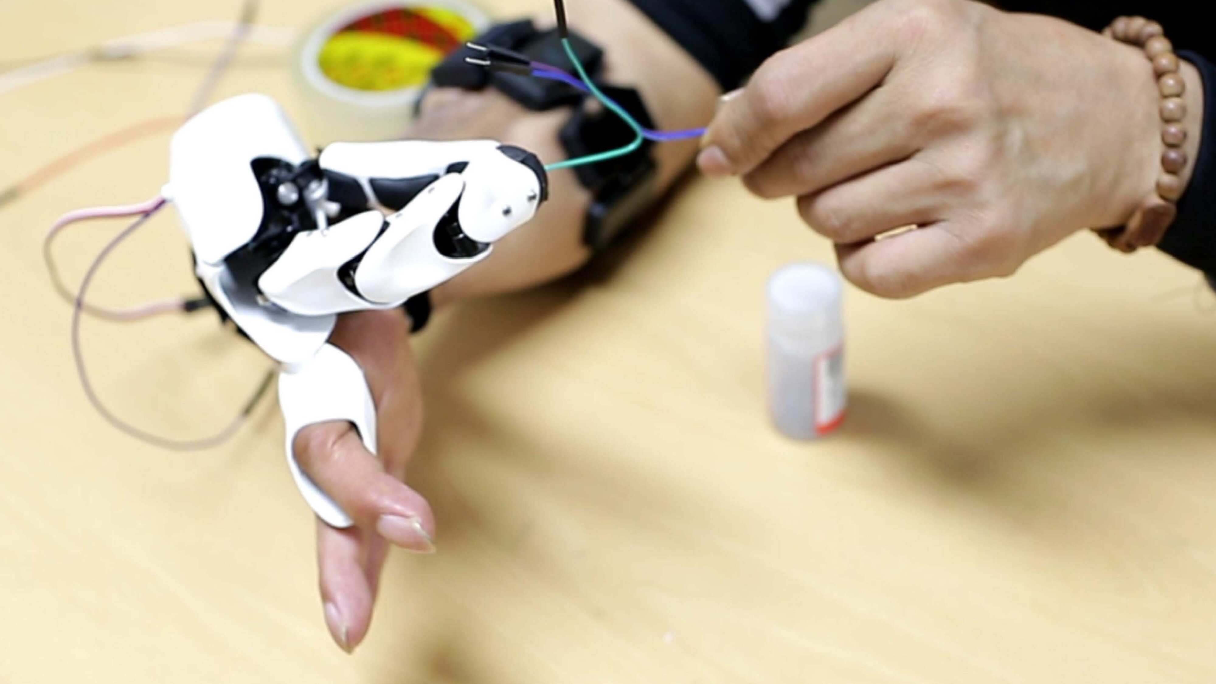
Evaluated the hardware through direct patient trials performing real-world Activities of Daily Living (ADLs). The validation included the standardized Box and Block test, power grasping (e.g., bottle opening), and fine-motor tasks like cable pinching (e.g., separating 1.3 mm diameter wires, a critical occupational requirement for the electrical engineer patient).
The prosthesis proved highly reliable, allowing the patient to execute stable grasps with repeatable performance. This real-world testing validates that the linkage-based underactuation and robust transmission successfully restore functional utility to the user.
Direct-Drive Tendon-Actuated Robotic Finger (PoC Prototype)
Objective: To investigate the dynamic transmission characteristics of a tendon-driven linkage using direct-drive (DD) actuators, focusing on high-bandwidth force control and precision cable routing.
Design Focus: Mitigating common tendon failures (slack, backlash, and wear) through empirical material selection (steel vs. braided cables) and the design of custom compact tensioners and robust anchors.
Led the end-to-end rapid prototyping from clean-sheet mechanical design to electronic bring-up and closed-loop control implementation. Integrated four DD actuators to eliminate gearbox friction and tuned a Cartesian impedance controller for dynamic disturbance rejection.
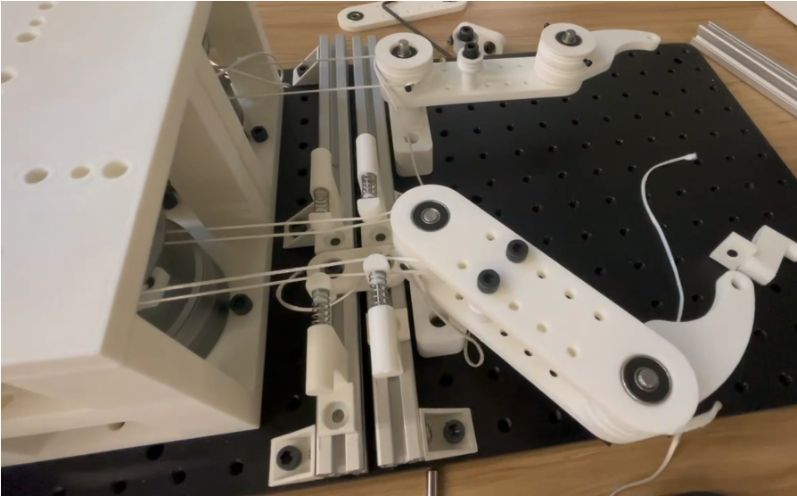
- Iterative Material Selection: Empirically evaluated various transmission mediums to solve critical routing issues. Transitioned from rigid steel cables (high friction/kinking) to fishing lines (high stretch/creep), ultimately standardizing on Dyneema (SK78) to eliminate backlash, minimize friction over tight bend radii, and ensure high-fidelity force transmission.
System Architecture: Design & Fabrication
Translating custom cable routing and tensioning strategies from CAD to physical hardware.
Kinematic Functionality
Validating the core coupled multi-DoF motions driven by the direct-drive tendon network.
Dynamic Compliance & Impedance Control
Evaluating hardware-in-the-loop Cartesian impedance control across variable compliance levels (Low, Medium, High gains).
BiFlex – Passive Variable-Stiffness Robotic Wrist
Challenge: Rigid robotic wrists provide precision but transmit dangerous forces during collisions. Compliant wrists are safer but lose the accuracy required for precise pick-and-place tasks in unstructured environments.
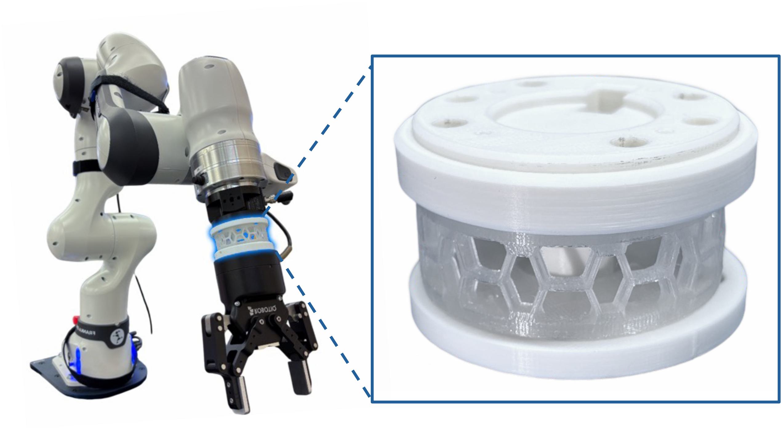
Insight: A 3D-printed inclined honeycomb structure that exploits the Euler buckling principle. It provides bimodal stiffness—acting as a rigid wrist for nominal manipulation and passively buckling into a compliant mode when impact forces exceed a safe threshold.
Led the end-to-end development from concept to validation. Formulated the lumped-spring theoretical model, conducted FEA structural analysis, designed the modular physical prototypes, and executed real-world robotic validations. Additionally, integrated the hardware with a 7-DoF robot arm (Panda - Franka Emika) using a Linux-based real-time controller to empirically validate dynamic contact-rich tasks. Published CAD files to enable integration with various commercial grippers.
Kinematic & Structural Rationale
- Passive Bimodal Stiffness: Removes actuator and control complexity while yielding safe contact and precise placement purely through mechanical intelligence.
- Structural Integration: Designed a custom universal joint interface passing through the center to constrain undesired yaw motion, ensuring purely compressive deformation during pre-buckling operations.
• Precision Payload: ≤ 500 g
• Wrist Height / Deflection: 40 mm / < 1 cm
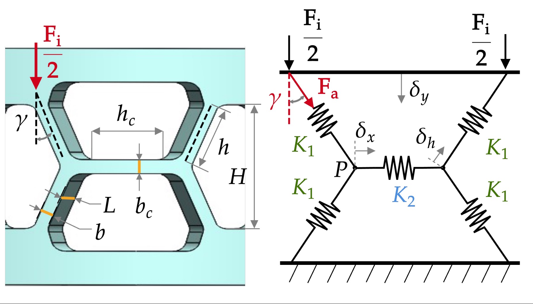
Geometry Tuning & Mathematical Modeling
Derived a lumped-spring analytical model (Pcr = π²EI / h²) to predict buckling behavior. Rather than relying on trial and error, the critical load was mathematically tuned to match everyday manipulation requirements.
By adjusting key geometric parameters—specifically the wall angle (γ) and beam width (b)—the stiffness and transition point were precisely calibrated. This theoretical approach showed extremely high correlation with static/buckling FEA simulations and physical Instron tests.
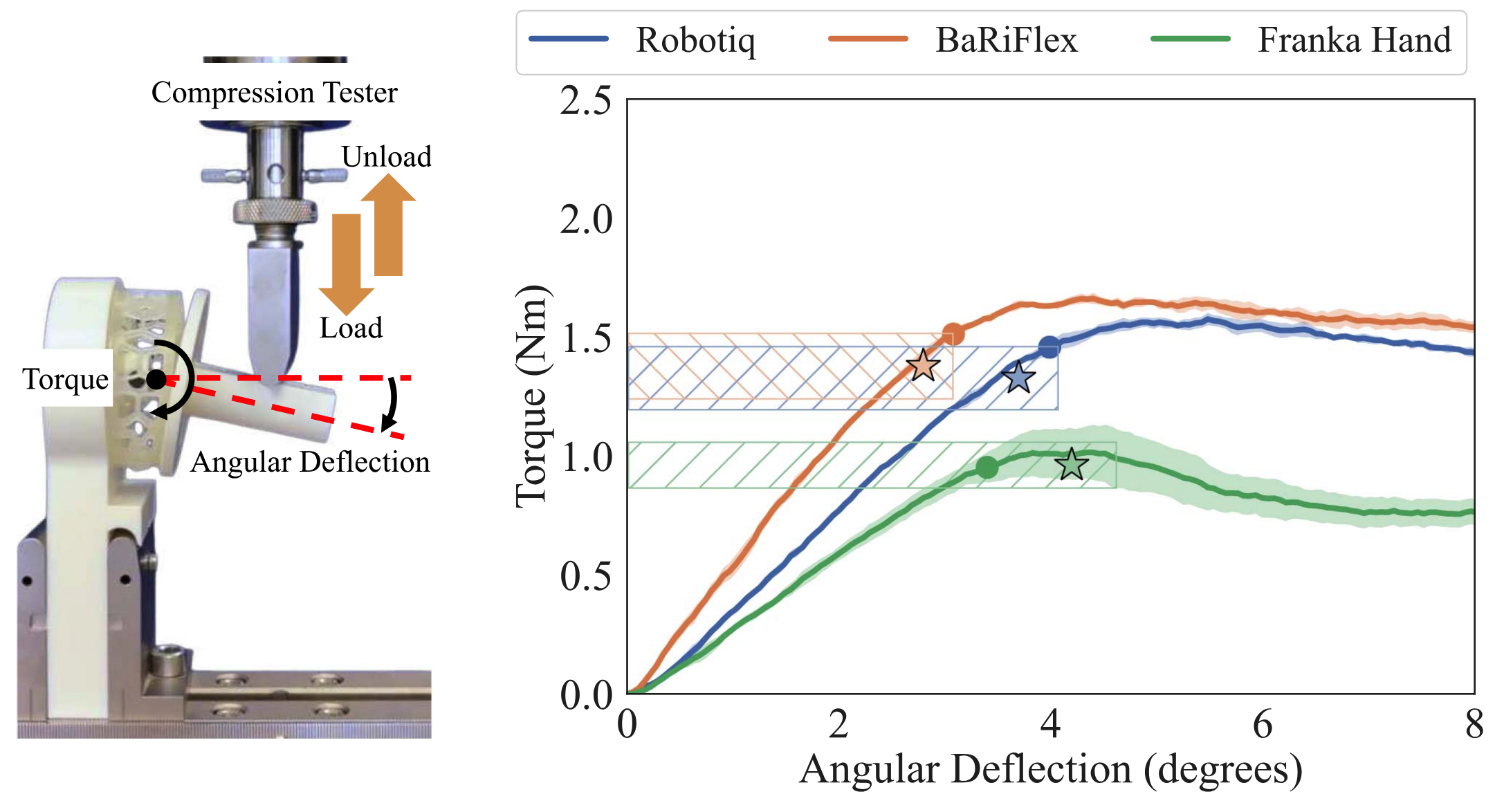
Mechanical Characterization & Validation
To bridge the gap between theoretical models and real-world hardware, rigorous mechanical characterization was conducted using a compression testing machine.
The empirical Torque vs. Angular Deflection curves proved that the physical prototypes precisely matched the mathematical predictions. The wrist maintained high linear stiffness (precision mode) until the exact engineered buckling threshold, whereupon it transitioned cleanly into a low-stiffness plateau (compliant mode) with self-recovery capabilities.
Modularity & Swappable Interface
Designed with strict Design for Manufacturing (DFM) and integration principles. The internal TPU honeycomb core remains standardized, while only the rigid top and bottom plates are swapped to fit different commercial systems.
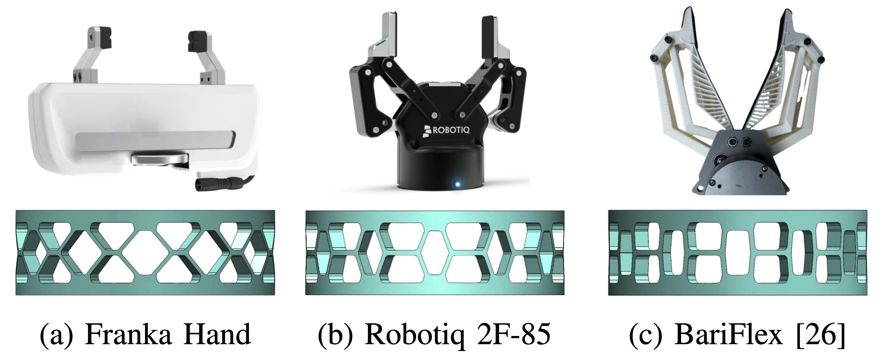
This highly modular architecture allowed the wrist to be seamlessly integrated with the Franka Hand, Robotiq 2F-85, and BaRiFlex grippers without needing to recalculate or re-print the compliant core, proving its viability as a universal robotic joint.
Adaptation in Contact-Rich Interaction (Wiping Test)
Direct side-by-side comparison of a standard rigid wrist vs. the BiFlex wrist reacting to unexpected environmental geometry.
Precision & Combined Task Validation
Demonstrating the dual-nature of BiFlex: maintaining absolute rigidity for precise payloads, while utilizing compliance to overcome perception errors.
Engineering Fundamentals – Precision Engine Lathe
Objective: Design, manufacture, and assemble a precision engine lathe capable of turning aluminum stock with tight geometric tolerances and minimal spindle runout.
My Role: Led the hands-on fabrication of the core spindle assembly—including milling for fastener clearances, lathe turning, and threading. Formulated the closed-loop mathematical error model to predict systematic geometric deviations across the entire machine.
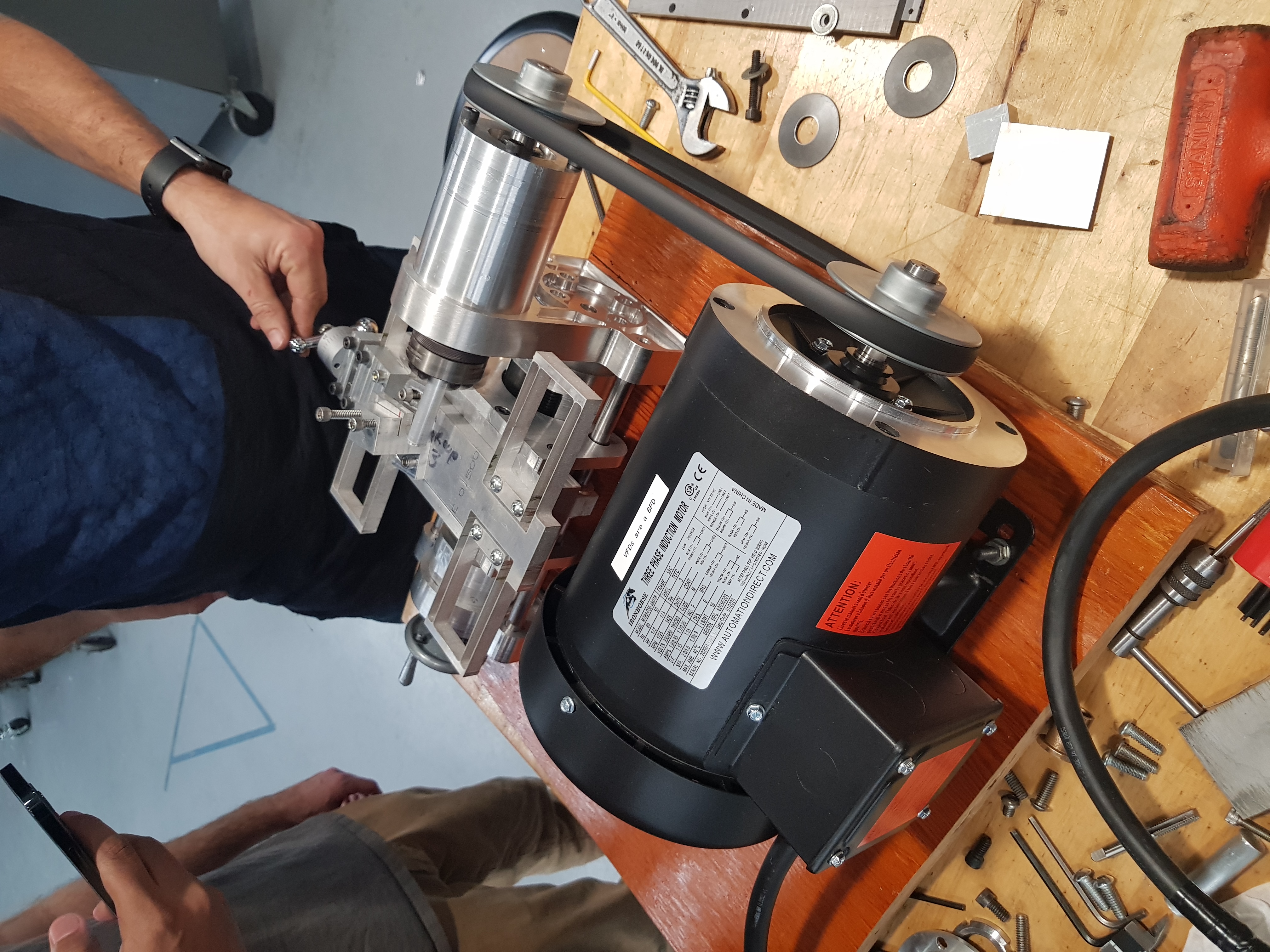
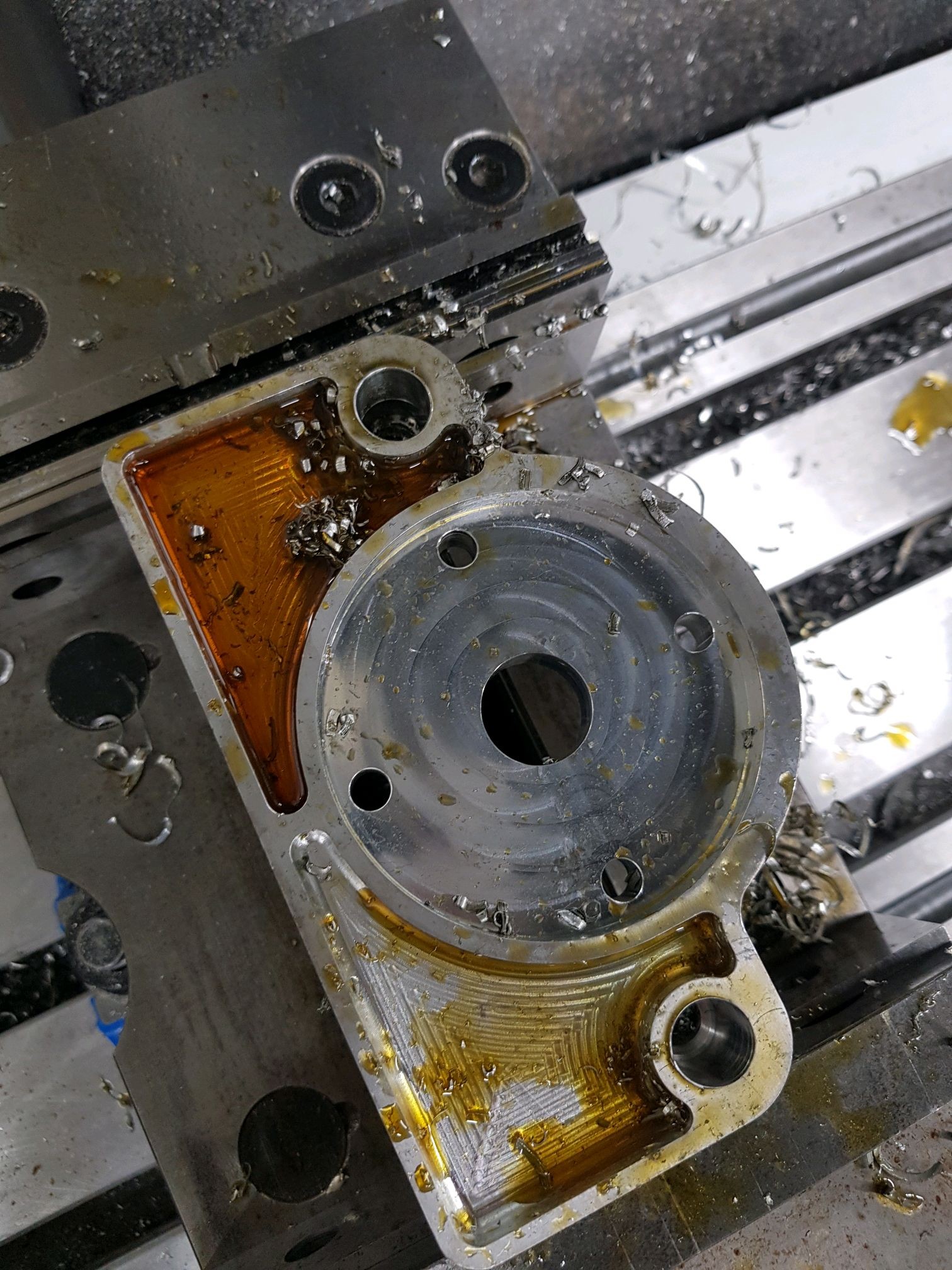
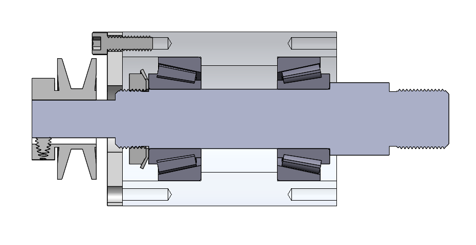
Spindle Design, Fabrication & Assembly
Translating precision CAD models into physical hardware through strict machining setups and assembly validation.
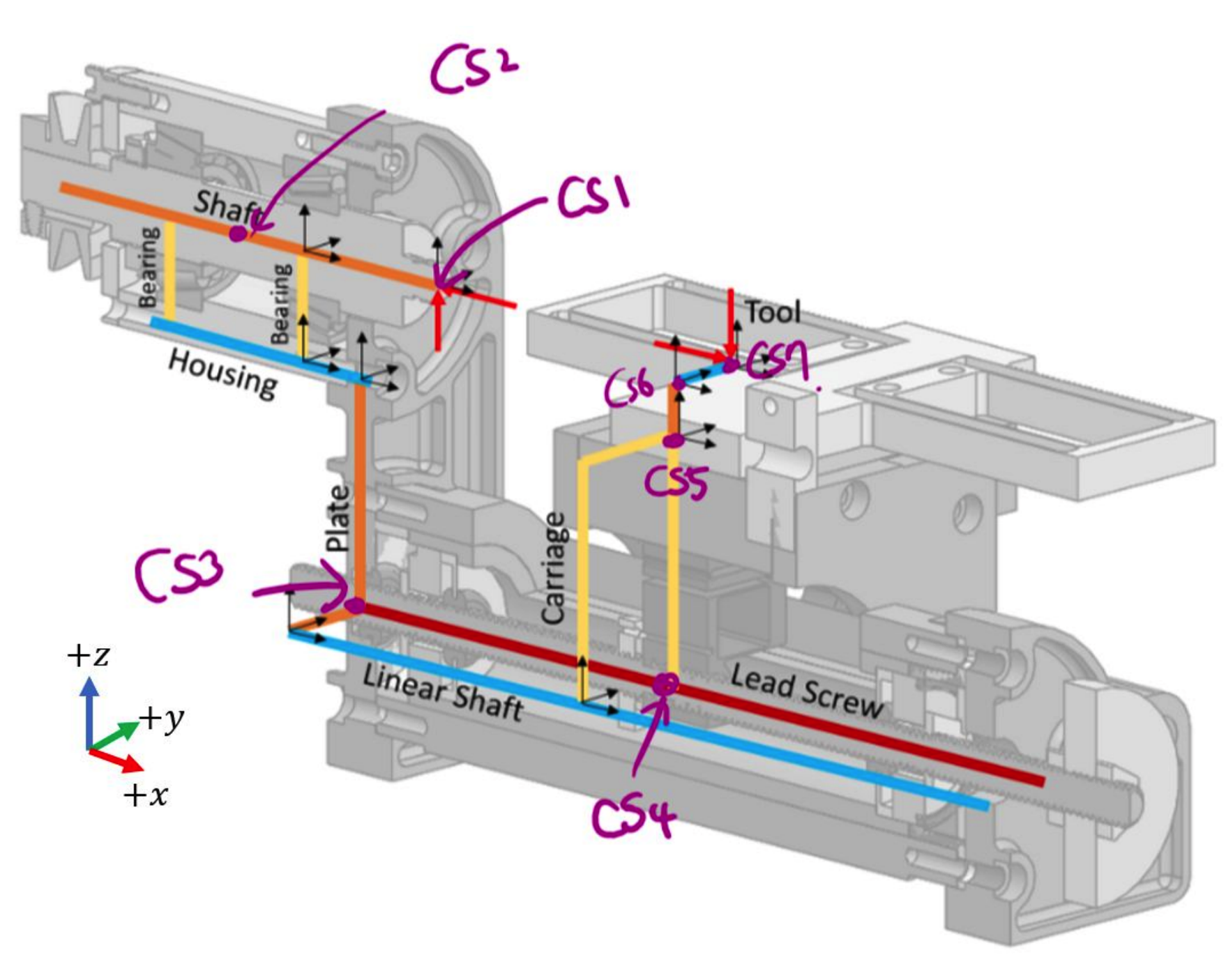
Mathematical Error Budgeting
To predict the overall machining accuracy, a closed-loop error model was formulated connecting the tool tip to the workpiece through seven distinct coordinate systems.
Using Homogeneous Transformation Matrices (HTM) and bearing stiffness estimations, the systematic geometric errors (e.g., structural deflections and assembly misalignments) were calculated. This analytical approach ensured that the structural stiffness and part tolerances were rigorously budgeted before any chips were cut.
Hands-on Fabrication & System Operation
Executing precision milling operations to assemble and validate the fully functional engine lathe.